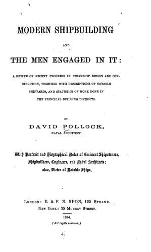
Modern shipbuilding and the men engaged in itPollock, David
History
Modern shipbuilding and the men engaged in it
Pollock, David
Shipbuilding -- Great Britain
It may be further explained that the sliding of the scale cylinder
until the new number is opposite the index point really involves two
operations: one sliding it till the end of the scale is opposite
the index point—which subtracts the logarithm of the divisor; and
the other sliding it till the next multiplier is opposite the index
point—which adds its logarithm to the previous result. Hence, when
the operations end with division the scale cylinder must be moved
till the end of the scale is opposite the index point.
The second scientific instrument to be noticed is the Polar
Planimeter, invented by M. J. Amsler-Laffon, Schaffhausen,
Switzerland, the object of which is to find the area of any figure by
simply tracing the outline with a pointer, the instrument—of which
the pointer is a part—doing all the rest; the results read off from
it having to undergo only a very simple and elementary calculation to
attain the desired result.
[Illustration: FIG. 25.
AMSLER’S POLAR PLANIMETER—(FIXED SCALE).]
Planimeters are made of several forms, the two kinds illustrated by
Figs. 25 and 26 being the most usual.[34] The planimeter shown by
Fig. 25 represents the instrument as made to one scale only, for
square inches of actual measurement. By its means the areas of, say,
cross sections of ship’s hull can be ascertained in an extremely
short time and with almost perfect accuracy, the readings taken
from the instrument having simply to be multiplied by a multiplier
consisting of the square of the number of units to the inch,
corresponding to the scale on which the sections are drawn, as 4 for
½-inch scale, 16 for ¼-inch, 64 for ⅛-inch, etc.
[Illustration: FIG. 26.
AMSLER’S PLANIMETER—(VARIOUS SCALES).]
The Planimeter shown by Fig. 26 is the instrument in a form adaptable
to various scales, but does not possess any very marked advantages
over the simpler form for the purposes of the naval architect or
marine engineer, so that notice of it must be brief. In this form
of the instrument the unit can be changed by altering the length of
the arm which carries the tracer to any of the scales for which the
instrument may be made available, and which are found divided upon
the variable arm. The scales which are usually provided for are as
follows:—
10 sq. in. = 10 square inches }
0·1 sq. f. = 0·1 square foot }
1 sq. dcm. = one square decimetre } Every total
0·5 sq. dcm. = 0·5 square decimetre } rotation of
2000 sq. m. } = 2000 square metres on a } the roller.
1 : 500 } scale 1 : 500 }
1000 sq. m. } = 1000 square metres }
1 : 500 } scale 1 : 500 }
Public-domain text, read in full here on John Shaqi.
Reviews
Reviews
No reviews yet
Be the first to share your thoughts on this work.
Elsewhere in the archive
Join the Discussion
Join the discussion
Sign in to leave a comment or review.
Sign InorCreate an account