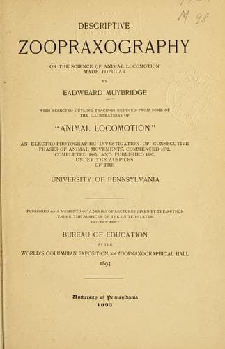
Descriptive Zoopraxography; or, the science of animal locomotion made popular — John Shaqi
Descriptive Zoopraxography; or, the science of animal locomotion made popularMuybridge, Eadweard
Science
Descriptive Zoopraxography; or, the science of animal locomotion made popular
Muybridge, Eadweard
Animal locomotion
In twelve of these compartments are arranged rollers, curtains, magnets,
etc., as previously described, and a compartment through which a focusing
lens is used. The two end compartments provide for the adjustment of the
camera, which is supported in the box to the rear of the exposing
arrangements. A cable of insulated wires for connecting the twelve magnets
with the exposing motor, contains a wire for the return current. As seen in
the engraving, seven of the magnets by the passage of their respective
currents have completed their releasing operations. In the eighth
compartment the two apertures in the exposing band are in the act of
effecting an exposure. The remaining four magnets are awaiting their turn
for action.
Figure 5 is a photographic camera divided into thirteen compartments, each
having a lens of the same construction, and the same focal length; these
are arranged to correspond with the compartments in the electro-exposors.
One of the lenses is provided with a focusing screen, and with it the other
twelve lenses are adjusted to a proper focus without removing the plate
holder behind them from its position in the camera.
The plate holder is constructed to hold three dry plates, each three inches
by twelve inches; the front is divided into twelve compartments, each three
inches square.
[Illustration: Fig. 5.]
Light is excluded from the front by a roller blind, strengthened by thin
narrow slats of hard wood; the blind works in grooves, is drawn over a
concealed roller, and covers the back of the holder when the plates are
being exposed.
Figure 6 is a rear and side view of the circuit maker, conventionally
called the exposing motor.
The motive power is an adjustable weight attached to a cord which is wound
around a drum. Twenty-four binding posts are attached to the table at the
back of the exposing motor; other binding posts are arranged for return or
other currents.
Figure 7 illustrates a front and side view of the upper part of the
exposing motor. Fastened to the frame is a ring of hard rubber, in which
are inserted twenty-four insulated segments of platinum-coated brass; these
segments are connected by insulated wires to the twenty-four binding posts
on the back of the motor table, figure 6.
[Illustration: Fig. 6.]
A shaft, connected by an arrangement of geared wheels to the drum, passes
through the center of the segmented ring and carries a loose collar; a
stout metal rod is firmly attached near its longitudinal center to this
loose collar. One arm of the rod carries a laminated metal scraper, or
contact brush, arranged to travel around the periphery of the ring, and in
its revolution to make contact with each segment in succession. The contact
brush is connected through the arm with one pole of the battery; and each
segment--through its independent wire and magnet of the
electro-exposors--with the other pole.
[Illustration: Fig. 7.]
[Illustration: Fig. 7.]
Public-domain text, read in full here on John Shaqi.
Reviews
Reviews
No reviews yet
Be the first to share your thoughts on this work.
Join the Discussion
Join the discussion
Sign in to leave a comment or review.
Sign InorCreate an account