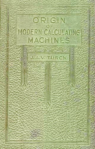
Origin of modern calculating machinesTurck, J. A. V.
History
Origin of modern calculating machines
Turck, J. A. V.
Calculators
Each numeral wheel is provided with a gear marked G, which, as the
carriage moves after writing or printing each figure of the item, is
supposed to slide into mesh one at a time with an adding gear marked
H, the engagement taking place from right to left. Or beginning with
the right or units numeral wheel a higher order numeral wheel gear is
supposed to shift through movement of the carriage into engagement with
the adding gear H, each time a key is depressed.
The adding gear H, is supposed to receive varying degrees of rotation
from the keys according to their numerical marking and to rotate the
numeral wheel with which it happens to be engaged, a corresponding
number of its ten marked points of registration.
Between the adding gear H, and the keys which act to drive it, is a
ratchet and gear device consisting of the ratchet pawl pivoted to the
adding gear H, the ratchet I⁶, and its pinion gear, the segment gear
I² fast to the rock shaft I, the nine arms I¹ fast to the rock shaft
and the pins I², which are arranged in the key levers to contact with
and depress the arms I¹ of the rock shaft varying distances, according
to the value of the key depressed. That is, supposing that the full
throw of the key-lever was required to actuate the rock shaft with
its gear and ratchet connection to give nine-tenths of a revolution
to the numeral wheel in adding the digit nine, the pin I² in the (9)
key-lever would in that case be in contact with its arm I¹, of the
rock shaft, but the pins I², of each of the other key levers would be
arranged to allow lost motion before the pin should engage its arm I¹
of the rock shaft, in accordance with the difference of their adding
value.
According to the specification, Ludlum evidently had the idea that he
could stop the adding gear H, while under the high rate of speed it
would receive from a quick depression of a key, by jabbing the detent
J between the fine spacing of the gear teeth shown in his drawing.
But to those familiar with the possibility of such stop devices, its
inoperativeness will be obvious; not that the principle properly
applied would not work, for its application by Felt prior to that of
Ludlum proved the possibilities of this method of gauging additive
actuation.
The detent lever J, as shown in the drawings, is operated by the hinged
plate D, through action of the key levers, as any one of them are
depressed.
Under depression of a key, the hinged plate D, being carried down with
it, engages the arm J³ of the detent and throws the tooth at its upper
end into the teeth of the gear H.
Public-domain text, read in full here on John Shaqi.
Reviews
Reviews
No reviews yet
Be the first to share your thoughts on this work.
Join the Discussion
Join the discussion
Sign in to leave a comment or review.
Sign InorCreate an account